

1. Overview of Multilayer Ceramic Technologies
Multilayer ceramic technologies are foundational to modern electronics manufacturing. Three primary variants dominate the field:
· MLCC (Multilayer Ceramic Capacitor)
· LTCC (Low-Temperature Cofired Ceramic)
· HTCC (High-Temperature Cofired Ceramic)
Their distinctions lie inmaterial selection,sintering temperatures,process details, andapplication scenarios.
2. Technical Specifications Comparison
|
Parameter |
MLCC |
LTCC |
HTCC |
|
Dielectric Material |
Barium Titanate (BaTiO₃), TiO₂, CaZrO₃ |
Glass-Ceramic, Ceramic-Glass Composite |
Al₂O₃, AlN, ZrO₂ |
|
Metal Electrodes |
Ni/Cu/Ag/Pd-Ag (internal); Cu/Ag (terminals) |
Ag/Au/Cu/Pd-Ag (low-melting alloys) |
W/Mo/Mn (high-melting metals) |
|
Sintering Temp. |
1100–1350°C |
800–950°C |
1600–1800°C |
|
Key Products |
Capacitors |
Filters, Duplexers, RF Substrates, Antennas |
Ceramic Substrates, Power Modules, Sensors |
|
Applications |
Consumer Electronics, Automotive, Telecom |
RF/Microwave Circuits, 5G Modules |
Aerospace, High-Power Electronics |
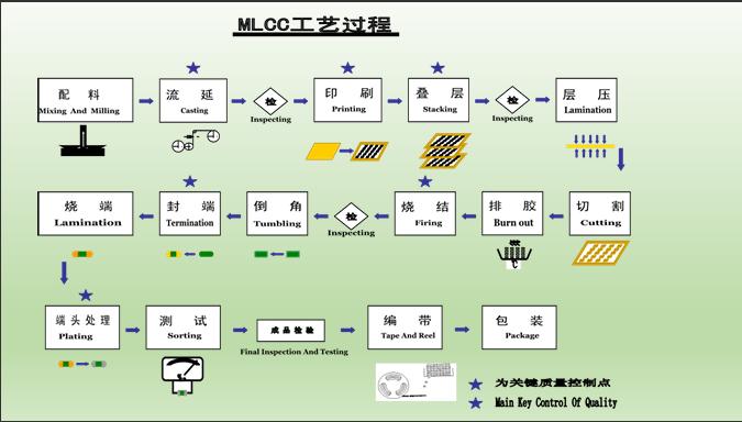
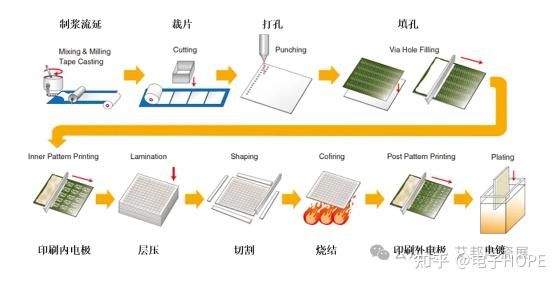
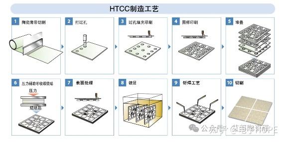
3. Manufacturing Process Flow
Shared Core Steps:
1. Tape Casting: Forming green ceramic sheets (thickness: 10–100μm).
2. Screen Printing: Depositing electrode patterns (e.g., Ag paste for LTCC, Ni for MLCC).
3. Lamination: Stacking layers under pressure (20–50 MPa).
4. Sintering: Firing in controlled atmospheres (N₂/H₂ for MLCC, air for LTCC/HTCC).
5. Termination: Applying external electrodes (e.g., Ag plating for MLCC).
Critical Differences:
· Via Drilling: LTCC/HTCC require laser-drilled vias for vertical interconnects; MLCC skips this step.
· Sintering Atmosphere:
· Layer Count:
4. Performance Trade-offs
|
Metric |
MLCC |
LTCC |
HTCC |
|
Capacitance Density |
100 μF/cm³ (X7R-grade) |
N/A (non-capacitive focus) |
N/A |
|
Thermal Conductivity |
3–5 W/m·K |
2–3 W/m·K |
20–30 W/m·K (AlN-based) |
|
CTE Matching |
Poor (vs. Si) |
Moderate |
Excellent (Al₂O₃ ≈ 7 ppm/°C) |
|
High-Frequency Loss |
Tan δ < 2% (at 1 MHz) |
Low insertion loss (<0.5 dB @ 10 GHz) |
Stable up to THz frequencies |
5. Emerging Innovations
· Ultra-High Layer MLCC: TDK’s 0.4μm-layer technology achieves 220μF in 0402 packages.
· 3D LTCC Integration: Kyocera’s embedded passives reduce RF module size by 60%.
· HTCC for Extreme Environments: CoorsTek’s AlN substrates withstand 1000°C in aerospace sensors.
Conclusion: MLCC, LTCC, and HTCC technologies address distinct needs across the electronics spectrum. MLCC dominates miniaturized passive components, LTCC enables compact RF systems, while HTCC excels in harsh-environment applications. Process optimizations—from material science to via architecture—drive their continued evolution in 5G, EVs, and advanced aerospace systems.


")


