

MLCC (Multi - layer Ceramic Capacitor) is a widely used type of capacitor. Its structure is formed by interleaving and stacking ceramic dielectric films printed with internal electrodes, sintering them at high temperature to form a ceramic block, and then sealing metal layers at both ends. It consists of three parts: ceramic dielectric, metal internal electrodes, and metal external electrodes. MLCC has the advantages of small volume, large capacitance, low loss at high frequencies, suitability for mass production, low price, and good stability. It meets the requirements of light, thin, short, and small information function products and is an important component in modern electronic products. What is the manufacturing process of MLCC?
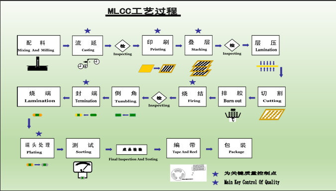
1. Batching: Ceramic powder, binders, solvents, and various additives are mixed in proportion and subjected to ball milling or sand milling to form a uniform and stable ceramic slurry. It generally consists of ceramic powder, solvent, dispersant, binder, etc. The solvent is a mixture of toluene and ethanol in a certain proportion. The dispersant is a surfactant that prevents ceramic powder from agglomeration. The binder is a polymer resin that can maintain the distance between ceramic powders and provide strength.
2. Tape Casting: The ceramic slurry is applied to a circulating silicone film through the pouring port of the tape casting machine to form a uniform thin layer. Then, most of the solvent is volatilized in the hot air zone and dried by heating to form a film with a thickness of 1um - 20um and uniform density.
3. Printing: The internal electrode slurry is printed on the ceramic film using a screen plate, and after drying, a clear and complete dielectric film is obtained. There are four types of printing: relief printing, intaglio printing, planographic printing, and screen printing.
4. Laminating: The printed dielectric films are neatly stacked into a block with a uniform thickness according to a certain misalignment. During lamination, the films are cut and peeled off. Ceramic film protective sheets need to be added to the bottom and top to enhance mechanical strength and insulation.
5. Layering and Pressing: The laminated block is subjected to isostatic pressing to make the laminated films closely combine, improving the compactness of the ceramic body after sintering. It is usually pressed in water to maintain uniform pressure, and slice sampling is required to ensure quality.
6. Cutting: According to the product design requirements, the laminated block is cut horizontally and vertically with a sheet - like thin blade to produce independent capacitor green bodies.
7. Binder Removal: The cut ceramic green bodies are subjected to heat treatment to remove organic substances such as binders.
8. Sintering: The chip after binder removal is made into a ceramic body with intact internal electrodes, good compactness, qualified size, high mechanical strength, and excellent electrical performance, which is divided into two stages: densification and reoxidation.
9. Chamfering: The sintered capacitor is not conducive to connection with external electrodes, so it needs to be ground and chamfered. The capacitor, water, and grinding media are put into a chamfering tank, and surface burrs are removed by means of ball milling, planetary milling, etc., to make the chip surface smooth and fully expose the internal electrodes on the end face.
10. End Sealing: The end slurry is applied to both ends of the exposed internal electrodes of the chamfered chip using an end sealing machine to connect the internal electrodes on the same side to form external electrodes.
11. End Firing: During the end firing of MLCC, first, the chip with conductive slurry coated on the end face is subjected to low - temperature binder removal to remove the binder, and then high - temperature sintering is carried out according to the type of slurry, so that the metal powder forms a conductive network, and the glass phase enhances the combination with the ceramic, finally forming a firm external electrode, laying a foundation for subsequent welding and circuit connection.
12. Electroplating: The product after end firing is subjected to end treatment. In an electrolyte solution containing nickel and tin ions, the end electrode of MLCC is used as the cathode, and a low - voltage direct current is applied to deposit nickel and tin on the cathode respectively to form a coating.
13. Testing: The capacitance, loss, insulation, and withstand voltage performance of the product are 100% tested and sorted, defective products are eliminated, and they are classified according to capacitance ranges.
14. Appearance Inspection: The appearance of the product is inspected, and products with poor appearance are eliminated.
15. Taping: The tested MLCCs are loaded into carrier tapes and rolled into plastic reels in fixed quantities.
16. Packaging: It involves attaching identification labels and packing before transportation.


")


")